Volkswagen Mark IV Forum banner

Footwell lights - where can i tap into interior map lighting?

7.2K views 35 replies 7 participants last post by  adam-  
#1 ·
I'm planning on adding some sort of footwell lights to my interior. Is there an easy location where i can tap into the interior lights so they will come on when the doors open/unlock like the map lights do.

I've currently removed most of the dash trim parts under the steering wheel so have full access to the fuse relay there. is there anywhere on that i could maybe run a tiny wire off for this purpose?

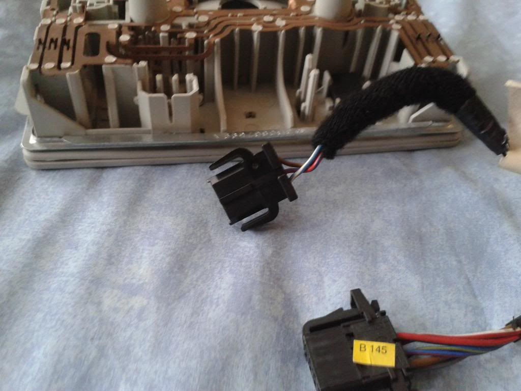
only other thing i was thinking is trying to run it directly from the map light somewhere, i've run two spare wires under the headlining to the map light area just incase
Image
 
Discussion starter · #4 ·
[quote user="Andreas"]

If you take the wire from the puddle light, then each footwell light will come on when the respective door is opened
Image


[/quote]

cheers Andreas, main problem with that is i would have to run a wire from the puddle light through the door grommet which means taking door cards off again . I've just run new speaker wires through there and put doorcards back on
Image


shouldn't be too much effort but think i'd prefer them to come on both together when either door is opened so interior map light probably better option for me
Image


Image


anyone know which of those 3 wires is the door/unlock sensor wire? guessing its not the brown so must be either the red/blue or white/blue?

[quote user="RobMmkay"]

I'm not at home so I can't check, but
if you have a Haynes manual, take a look at the wiring diagram for the
Map Light (starts at pg 12:20 I think?) and find the cables that go to
the light itself. There will be no issues in tapping off the feed at the
light if you already have wires in place.

[/quote]

cheers buddy would probably be a good idea to get one of those haynes manuals for my car
Image
but if do get a spare mo when you at home if you wouldnt mind having a look would be appreciated mate, that's if i haven't solved it by then
Image
Image
 
Discussion starter · #7 ·
[quote user="RobMmkay"]

At work at the mo with a shoot-slow PC else I'd search the Googles for a diagram, but I'll take a pic and upload about 4:30 if you want to get on with it tonight :)

[/quote]

cheers buddy yea that would be great want to try finish putting all the trim parts back together/sort all the wiring after work 2nite!
Image
Image
 
Discussion starter · #10 ·
thanks for the above two posts awesome stuff
Image


@Imagewerx will it be ok just running two low power footwell or glovebox lights without relay?

also i thought i could just ground off anyone of the brown wires and it was the positive 12v wire that controlled the on/off with the central locking?

so its actually controlled by the switched ground wire (blue/grey) not the positive 12v (red/blue?)

so basically i need to use blue/grey as the ground instead of brown and red/blue as the positive?

Thanks!
 
Discussion starter · #12 ·
well at the moment i will just be using 2 spare vanity lights until can fiind a better footwell light, just want to sort the wiring all out now so i wont need to take the pillars and trim parts off again.

was thinking about running the main vanity lights off this also so wuld be 4 x lights but may just leave them 2 main ones on a seperate switch and wire the other two into the central locking switched ground if that would be safe?

cheers
 
Discussion starter · #13 ·
[quote user="Imagewerx"]

No as it's switched ground to control the interior lights and not switched live,has been like this on neg ground cars since some bloke called Noah saw the weather forecast and started building a large boat
Image
.

Can you link to what you'll be using please?

[/quote]

Cheers Chris that combination was bang on worked a treat
Image
its switching on and off just as i wanted
Image


So i will now be using either two spare 3rd brake lights i've got or 2 puddle lights. the vanity lights were not bright enough.

Image


question is how many of these lights can i safely run without any problems. could i use all 4 lights or would that be too much for it to handle?
 
Discussion starter · #20 ·
thanks dude think you may have saved me from blowing my interior lighting!
Image


I've just run those two wires off the pillar connection and taped them up for now until i can sort that relay out. buzz sound is fine cheers for the warning, hopefully wont bother me or may even sound cool!
Image
Image
 
Discussion starter · #21 ·
[quote user="Imagewerx"]

[quote user="VictorE"]

could i use all 4 lights or would that be too much for it to handle?

[/quote]

As soon as you have to ask this question the answer is always automatically yes.The interior light output from the CCM is a MOSFET (a kinda posh transistor) which is needed to make it fade out and it's only designed to run a single festoon bulb with just a LITTLE bit let over to play with (I'm only guessing here as that's how these things are normally built).

Do this with a standard 4/5 pin relay......

Pin #85......................blue/grey
Pin #86......................red/blue
Pin #30......................a new 12 volts fused supply
Pin #87......................out to lights

.....and you can have as much driven off this circuit as the fuse will allow.

[/quote]

so got me a 5pin 30amp relay from halfords and trying to wire it up..

for pin 87 going to the lights do i run two wires from this pin out to lights or is it only 1 wire coming out from Pin #87? if only 1 is this the positive or ground going out to lights.. where do i connect the other side light to please?

also can the 12v wire supply to pin 30 be from a red/brown wire like the one from the ashtray or does it have to be solid red?

Do I REALLY need this relay if i am using very low power LED bulbs instead of the filament bulbs, as apparently they consume a lot less power so would it be ok to just add two extra bulbs without the relay if i am swapping ALL the filament bulbs for leds in my interior? should still be within safe limits as they draw much less power even if there are a pai of extra bulbs?

cheers
 
Discussion starter · #23 ·
[quote user="Imagewerx"]

It doesn't matter how many wires from pin #87,you can run them both back to the relay or take one thicker wire off to the LEDs and join both of them onto it,both methods will work just the same.What you have to connect the 4 pins to is explained above,I really can't make it any simpler than that? Any permanent live will do as not all of them are solid red,the *** lighter is as are the two red/whites in the radio's ISO loom.

Yes you REALLY do need the relay for the reasons I went to a lot of trouble to explain above
Image
.If you're replacing all the filament bulbs it needs a proper resistive load to work properly,just LEDs will never give you this.But as the resistance of the relay coil is a lot higher than that of a couple of filament bulbs,it might still not work properly.These CCMs are not designed to drive LEDs,so don't be surprised if they don't work properly.

[/quote]

Ok well this has gone in the total wrong direction..I now have no central locking/windows or interior lights
Image
Image
Big problem..

think
the wires must have touched or something when nothing was connected as i heard some crackling then
it all cut...any ideas what I have done im hoping it could just be a
fuse..?

took the fusebox cover off and when i started the car a
green 30amp fuse dropped out from somewhere. .it hasn't blown but i have
no idea where it came from?

Image


Image


please tell me i just need to put it back in one of those slots and it will all work again
Image
?
 
Discussion starter · #26 ·
ok so what i have learned the relay does is create a switched positive output (from the switched negative?) which comes out via 87/87a right? and i can run + power from this output to my 2 footwell lights.

what i need to know is where to draw the negative for the extra lights from can i just join another wire from 85a (blue/grey) on the relay to the other end of footwell lights (negative)?
 
Discussion starter · #28 ·
[quote user="Imagewerx"]

Not from 87A as that's normally closed.Negative for your lights is any chassis ground or solid brown wire,87 is positive out to your lights.

[/quote]

thanks very much.

i also maybe need to mention that ive got a
seperate switch wired into the circuit that powers my glovebox
light and sunvisor vanity lights, so even when the doors are
shut i can switch them on with that button, or they stay on when doors are unlocked with the central locking. the glovebox light is powered seperately from the
positive of the ashtray and to the switched ground with the vanity lights.

at
the moment its working EXACTLY how i want without the relay and just one extra festoon footwell
light attached but i just remembered id taken the main centre interior festoon bulb out all this time which is maybe why it was running fine. if i really need the relay I have to find the correct way to wire it in
with this extra seperate switch ive got.

can i join the blue grey wire safely at 85 with the other switch negative wire as below,
forgive the really dodgy temporary wiring i was just testing it out
Image


Image


(black/blue is the blue/grey from pillar and grey is the red/blue) the red wire joined on 85 is the negative from my switch that controls my glovebox/vanity lights also. and 87 is the output lights. 30 is the positive side of my other switch...

BUT tbh i dont think i need the additional +ve feed on 30 or 87 if i just add
the footwell lights to the 85 and 86 either side of the relay it still works how i want it to and it seems to also be protected by the relay? it was making that buzz sound you were on about when lights fade off/on
Image
is it possible to run the relay that way without connecting 30 and 87 up, the fuse inside should still protect the circuit? I don't really want to source another 12v supply if its not needed.

So basically the vanity lights, footwell lights and glovebox light come on with the central locking
Image
Image
 
Discussion starter · #30 ·
[quote user="Imagewerx"]

If it works,go with what you're happy with.

[/quote]

Image


Im really happy with the way ive got it wired up WITHOUT the relay and got a gut feeling that the stock system can hand two extra low powered bulbs without any problems so am gonna risk it i think..plus that ring/buzz sound from the relay would probably annoy me after a while... but thanks for the warning/advice
Image


it should still be protected by a fuse somewhere right if anything was to overload the circuit? (fuse 14?) Will take the chance as long as its not a wiring/fire hazard?

here a quick video of how its looking/working without the noisy relay. think im gonna leave it wired like this as it was running perfectly 2day
Image


Discussion starter · #32 ·
Image


sorry 4 not taking your advice dude its just wiring that relay was causing me more problems than i think its worth and i really dont want to put up with that buzz sound everytime the lights fade out.. so am looking into other options as You did say go with what your happy with which is no relay, but again thanks for your input
Image


just doing some research it seems relays are useful when you are driving a high current circuit off a low powered one, im only adding two tiny powered lights if they were high powered headlights or something it would defo need a relay i agree, but a couple of festoons should be ok, you did say yourself you were just guessing how much it can handle.. I have run two extra lights in my glovebox for nearly 6 months with no issues from the ashtray supply which is being shared with the red/blue supply to the footwell lights on this circuit so i honestly think it will be fine.

If anything goes wrong I take full responsibility and will have to fork out for damages but as you've said the worst that could happen is losing my interior lights i'll take that risk as long as its not a fire/safety issue which is what i was asking you.?

Can i not just add an inline fuse between the footwell lights and the 12v red/blue wire to protect the circuit instead of the relay?

if you don't want to help anymore i understand, we shall see if it holds up
Image